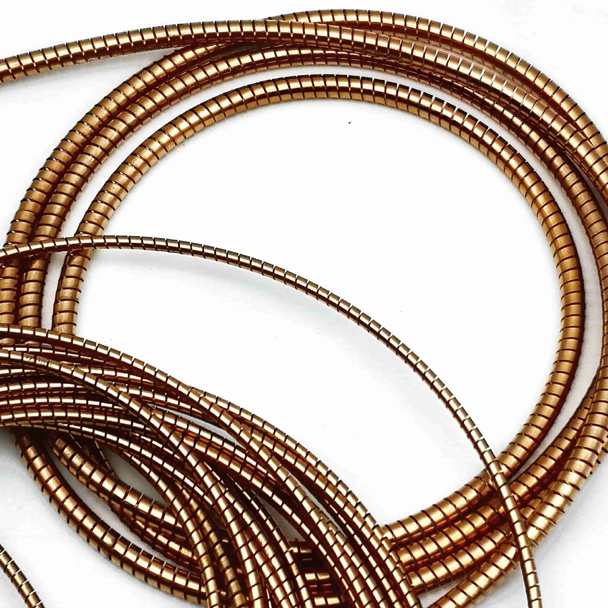
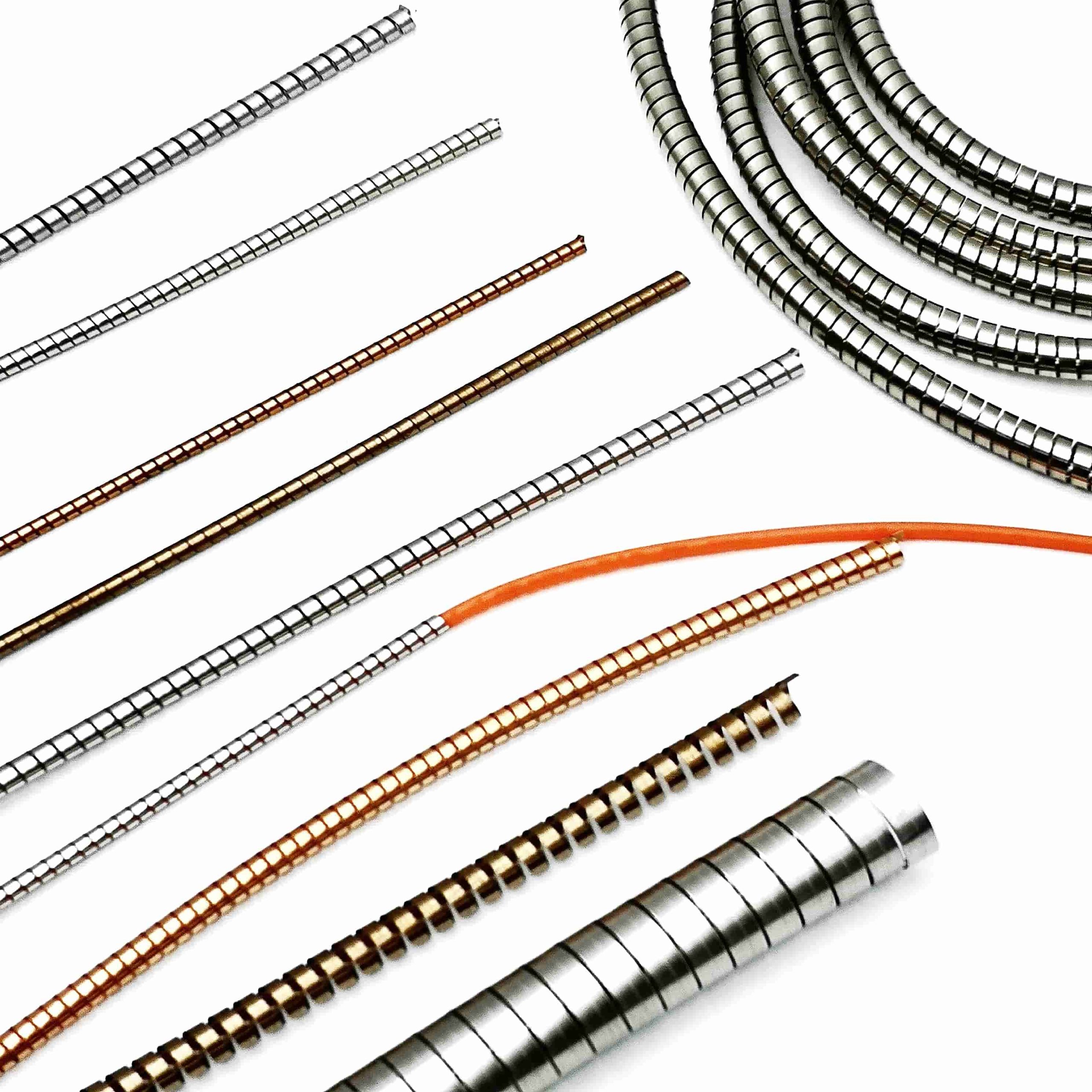
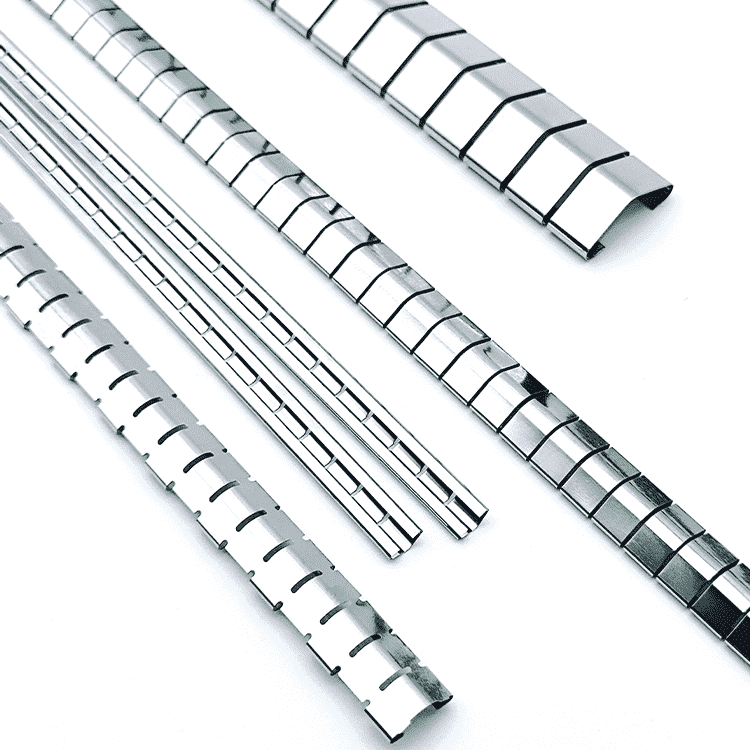
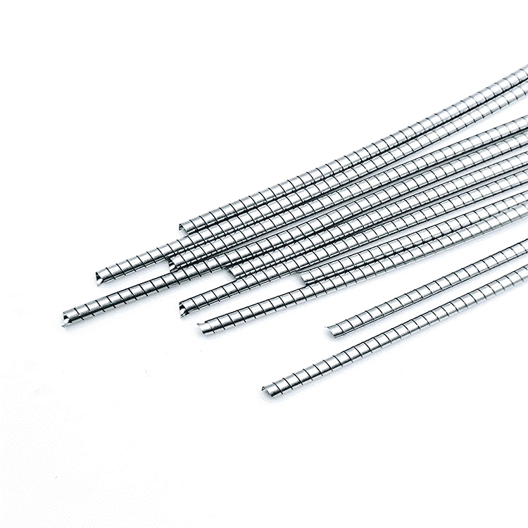
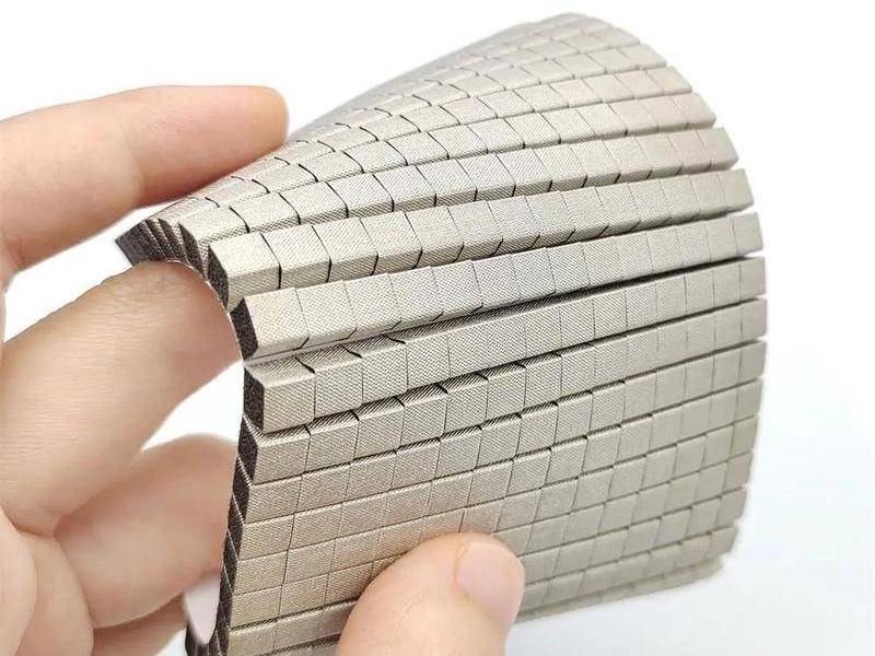
Spring finger contacts in PCB and SMD applications
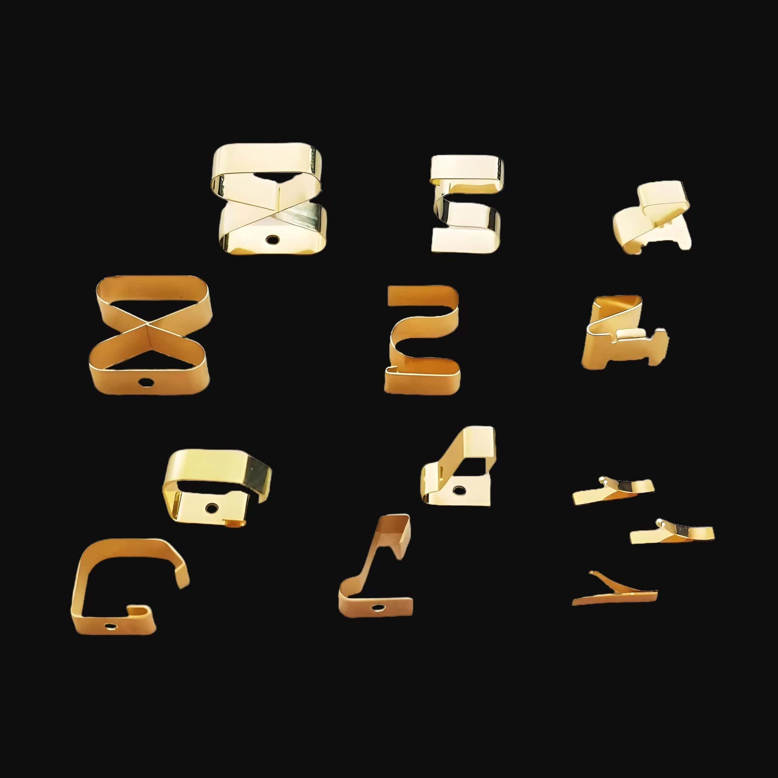

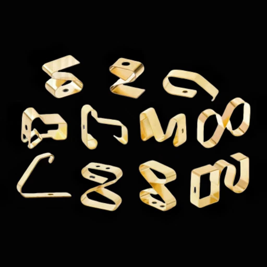
Spring finger contacts, commonly used in PCB and SMD applications, play a crucial role in circuit board design and manufacturing, especially where reliable electrical connections are required.

Spring finger contacts
Table of Contents
1. Basic Concepts
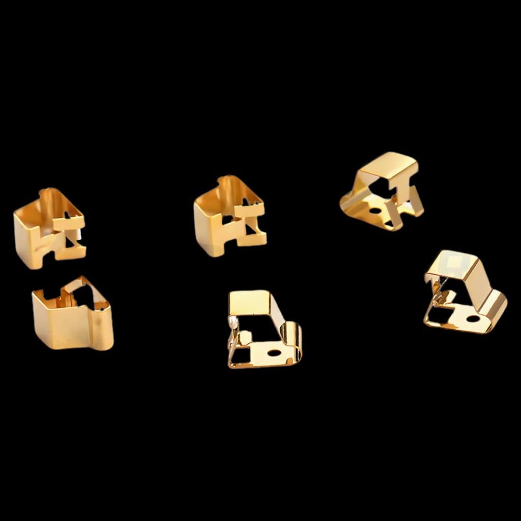
Spring finger contacts, also called “spring fingers” ,serve as connectors between PCBs and SMDs (Surface Mount Devices). They are typically employed where frequent insertion and removal or high reliability in connections are essential. Designed to offer low resistance and high-reliability connections, spring fingers also withstand a certain degree of mechanical stress, which adds to their durability in varying applications.
2. Application Scenarios
Spring finger contacts are valuable in numerous industries, given their ability to provide stable, dependable connections. Below are some common scenarios:
2.1 Consumer Electronics
In devices like smartphones, tablets, and laptops, spring finger contacts connect various small modules, such as SIM card trays, battery connectors, and antenna connectors. These components support the compact designs of consumer electronics by minimizing the need for complex wiring.
2.2 Industrial Equipment
In industrial control and automation equipment, spring fingers are used to connect sensors, actuators, and other modules, maintaining stable connections even in harsh environments where mechanical stress or vibration might otherwise compromise the connection.
2.3 Medical Devices
Reliable electrical connections are vital in medical devices for both safety and performance. Spring finger contacts are favored for their low resistance and high-reliability properties, supporting the precise and durable connections required in healthcare environments.
2.4 Automotive Electronics
In automotive systems, spring finger contacts are employed to connect sensors and control modules, especially where high-frequency signal transmission is necessary. Automotive-grade spring finger contacts must endure high temperatures, vibrations, and moisture.
3. Design Points
The design of spring finger contacts requires attention to materials, dimensions, contact force, and PCB pad design to ensure optimal performance.
3.1 Material Selection
Spring fingers are typically made from materials with excellent conductivity and elasticity, such as phosphor bronze and beryllium copper. These metals provide stable electrical connections and retain their shape after repeated insertion and removal cycles.
3.2 Size and Shape
To ensure proper contact with PCB pads, the dimensions and shape of spring fingers must be precisely designed. Common shapes include wavy, straight, and bent configurations, each providing different levels of flexibility and force.
3.3 Contact Force
The contact force of a spring finger significantly impacts its reliability. Excessive force can damage the PCB, while insufficient force may result in poor contact. Generally, contact forces between 0.1 N and 1 N are recommended, depending on application requirements.
3.4 PCB Pad Design
For optimal connectivity, the PCB pad should match the shape of the spring finger lead. Pad width should be slightly less than or equal to the lead width, while length varies depending on the component. No vias or through-holes should be within 0.5 mm of the pad to prevent solder drainage.

4. Manufacturing Process
Spring finger contacts are compatible with various manufacturing techniques, including SMT, hybrid processes, and double-sided SMT.
4.1 SMT Process
In the SMT process, spring fingers are mounted by applying solder paste, placing components, and performing reflow soldering. SMT offers high efficiency and is widely used for PCB assemblies.
4.2 Hybrid Process
For boards with both SMD and THT (Through-Hole Technology) components, a hybrid approach is adopted. Here, SMDs are mounted first and soldered via reflow, followed by THT components with wave soldering.
4.3 Double-Sided SMT
When components are mounted on both sides of a PCB, careful attention is required. Lightweight components should be chosen for double-sided mounting. If both sides have heavy ICs, solder materials with different melting points may be needed, which increases cost and complexity.
5. Performance Requirements
For spring finger contacts to perform optimally, they must meet specific thermal resistance, solderability, and response time requirements.
5.1 Thermal Resistance
Spring finger contacts must withstand high temperatures to maintain stability. Typical requirements include a heat exposure of (215 ± 20)°C for 20 to 60 seconds during reflow soldering and (260 ± 20)°C for 10 seconds during wave soldering.
5.2 Solderability
PCB pads must be smooth and treated for oxidation resistance to ensure high solder quality. Good solderability minimizes issues such as poor adhesion, which could compromise electrical connections.
5.3 Response Time
In applications where rapid response is critical (e.g., dynamic force sensors), spring fingers are expected to have short response times, typically around 26 milliseconds.

6. Testing and Validation
Thorough testing ensures the reliability of spring finger contacts over time. Key testing methods include:
6.1 Mechanical Testing
Mechanical tests evaluate the durability of spring fingers under repeated insertion and removal cycles, ensuring that they retain their shape and maintain reliable connections.
6.2 Electrical Testing
Electrical tests verify the conductivity and contact resistance of spring fingers, ensuring they meet required electrical standards.
6.3 Environmental Testing
Environmental tests simulate extreme temperature, humidity, and other conditions to verify that spring fingers maintain reliable performance under varied environmental stresses.
7. Optimization Tips
Implementing best practices in the design and production of spring finger contacts enhances reliability and reduces costs.
7.1 Standardization
Choosing standardized SMD components and packages allows for large-scale production and cost efficiency.
7.2 Layout Optimization
When designing the PCB, it’s essential to distribute heat evenly to ensure uniform reflow soldering. Proper heat distribution minimizes defects such as tombstoning, poor soldering, and solder ball formation.
7.3 Process Simplification
For complex assemblies, combining automated processes with manual soldering can improve efficiency and product quality.

Spring finger contacts are indispensable in modern electronic design, providing reliable connections for a variety of devices and environments. By understanding their design, material choices, and best practices for manufacturing and testing, manufacturers can ensure optimal performance and durability in their products.If you need these products,please contact us.
You May Also Like
-
 Handa spiral tubes with remarkable performance in EMI shielding applications
EMI/EMC Shielding | RFI Shielding | EMI Gaskets
RF/EMI Shield Spiral Gasket
Handa spiral tubes https://www.handashielding.com/request-a-quote.html Material Properties of Handa Spiral TubesEMI Shielding Performance in Various FrequenciesPerformance in Humid and Corrosive EnvironmentsApplications Across IndustriesInstallation and Maintenance ConsiderationsConclusion and Future Outlook Handa spiral tubes are known for their remarkable performance in EMI shielding applications, particularly in humid or otherwise challenging environments. This functionality is largely due to the unique characteristics of their material composition and surface treatments. These tubes have become invaluable across industries, including telecommunications, aerospace, military, medical, and precision instrumentation, where reliable EMI shielding is crucial. Here is an expanded look at the comprehensive advantages, applications, and technological features of Handa spiral tubes, focusing on their functionality in humid conditions and their material properties. Material Properties of Handa Spiral Tubes The effectiveness of Handa spiral tubes in EMI shielding applications is largely a result of the materials used in their construction. The primary materials are: Beryllium Copper (BeCu): High Conductivity: Beryllium copper is widely recognized for its high electrical conductivity, which enables efficient electromagnetic wave transmission. This quality makes BeCu an excellent material for EMI shielding, allowing it to absorb and reflect interfering signals. Elasticity and Mechanical Resilience: Beryllium copper has exceptional elasticity, which allows the tubes to compress and return......
-
 Spiral Shielding Gaskets providing electromagnetic interference (EMI) shielding
EMI/EMC Shielding | RFI Shielding | EMI Gaskets
RF/EMI Shield Spiral Gasket
Spiral shielding gaskets are essential components in various industrial applications, providing electromagnetic interference (EMI) shielding while ensuring reliable sealing. Their effectiveness, however, can be compromised in corrosive environments, making it crucial to enhance their corrosion resistance. This article explores the multifaceted strategies employed to improve the corrosion resistance of spiral shielding gaskets, covering material selection, surface treatment, design optimization, environmental testing, the use of composite materials, and maintenance practices. By understanding these strategies, manufacturers can ensure the durability and reliability of spiral shielding gaskets in demanding conditions. 1. Material Selection2. Surface Treatment3. Design Optimization4. Environmental Adaptability Testing5. Composite Materials6. Maintenance and CareConclusion Spiral Shielding Gaskets providing electromagnetic interference (EMI) shielding 1. Material Selection The foundation of a gasket's performance lies in its material. For spiral shielding gaskets, the choice of material directly impacts their corrosion resistance. 1.1 Stainless Steel Alloys Stainless steel is the most commonly used material for spiral shielding gaskets due to its inherent corrosion resistance. Among the various grades, 316L stainless steel stands out for several reasons: Molybdenum Content: The addition of molybdenum enhances 316L's resistance to pitting and crevice corrosion, particularly in chloride-rich environments, which are common in many industrial applications. Low Carbon Content: The low......
-
 EMI Shielding Finger Stocks to protect sensitive electronic equipment
EMI/EMC Shielding | RFI Shielding | EMI Gaskets
Fingerstrips
EMI Shielding Finger Stocks(Fingerstrips) Introduction to EMI Shielding Finger StocksBasic ConceptsKey Features and Types of EMI Shielding Finger StocksPerformance StandardsApplications of EMI Shielding Finger StocksInstallation MethodsAdvantages of EMI Shielding Finger StocksLimitations of EMI Shielding Finger StocksFuture DevelopmentsConclusion EMI Shielding Finger Stocks(Fingerstrips) are crucial components used in various industries to protect sensitive electronic equipment from electromagnetic interference (EMI). Made from specialized alloys such as beryllium copper, these materials ensure stable signal transmission while preventing external disturbances. This article will delve into the intricacies of EMI Shielding Finger Stocks, exploring their design, types, performance standards, applications, installation methods, advantages, limitations, and future developments. Introduction to EMI Shielding Finger Stocks Electromagnetic interference can significantly impact the performance and reliability of electronic devices. EMI Shielding Finger Stocks are engineered to mitigate these effects, providing a barrier that reflects or absorbs electromagnetic waves. Their unique design allows them to create effective seals in various electronic applications, ensuring that sensitive components remain protected from external interference. Basic Concepts EMI Shielding Finger Stocks consist of resilient metal strips with a "finger-like" structure. This design enhances the ability of the material to conform to irregular surfaces and create a reliable contact. Beryllium copper is often the material of......
-
 EMI Shielding Spiral Tube Gaskets
EMI/EMC Shielding | RFI Shielding | EMI Gaskets
RF/EMI Shield Spiral Gasket
EMI (Electromagnetic Interference) shielding spiral tube gaskets are critical components in many electronic and industrial applications, designed to protect sensitive equipment from electromagnetic interference while also maintaining structural integrity in challenging environments. One of the primary concerns with these gaskets is their susceptibility to corrosion, which can compromise their effectiveness and longevity. This article explores strategies to enhance the corrosion resistance of EMI shielding spiral tube gaskets, focusing on material selection, surface treatments, design optimization, and maintenance practices. Understanding EMI Shielding Spiral Tube GasketsFunctionality and ImportanceComposite MaterialsAdvantages of Composite MaterialsMaintenance and CareInspectionImportance of Regular InspectionCleaningBenefits of Regular CleaningConclusion EMI Shielding Spiral Tube Gaskets Understanding EMI Shielding Spiral Tube Gaskets EMI shielding spiral tube gaskets are engineered to create a reliable seal between two surfaces, preventing electromagnetic waves from penetrating and interfering with the operation of electronic devices. They are typically made from conductive materials that offer both mechanical flexibility and electrical conductivity. However, the presence of moisture, chemicals, or extreme temperatures can lead to corrosion, undermining their effectiveness. Thus, enhancing corrosion resistance is essential for ensuring their longevity and performance. Functionality and Importance EMI shielding spiral tube gaskets serve multiple functions, including: Electromagnetic Shielding: They block unwanted electromagnetic radiation, preventing......
-
 Electrically conductive foam for a wide range of applications
Shielding Gasket Solutions and Materials
Electrically conductive foam
Electrically conductive foam is an innovative material designed to combine the softness, flexibility, and compressibility of traditional foam with the ability to conduct electricity. This unique combination of properties makes conductive foam ideal for a variety of industries where both cushioning and electrical functionality are required, such as electronics, automotive, aerospace, medical devices, and military hardware. What is Electrically Conductive Foam?Key Characteristics of Electrically Conductive FoamApplications of Electrically Conductive FoamManufacturing Process of Electrically Conductive FoamAdvancements and Trends in Electrically Conductive FoamConclusion What is Electrically Conductive Foam? Electrically conductive foam is a specialized foam material that has been infused or coated with conductive materials such as carbon, silver, nickel, or copper. These conductive particles provide the foam with its unique ability to transmit electricity, allowing it to function as both a cushioning material and an electrically active component. The foam itself is typically made from polyurethane, polyethylene terephthalate (PET), or other flexible polymers, which provide the base mechanical properties such as compressibility, resilience, and environmental resistance. The conductive fillers are either mixed into the foam during production or applied as a surface coating, depending on the application’s requirements. Key Characteristics of Electrically Conductive Foam Electrically conductive foam offers several distinctive properties......
